![]()
ETE MODULE SPECIFICATIONS
by Dave Pryor and Stretch Andersen with illustrations by Tobias
Giles
http://www.ete.org
Copyright © 1995-99 by ETE. All Rights Reserved.
Revision 1: 3/16/99, updated electrical bus plug connectors.
Note: The original specifications first appeared in the ETE EXPRESS, issues #66 and #68. The format in this publication differs from the original publication since it has been modified for Web publishing.
Additional CAD Drawings
ETE MODULE SPECIFICATIONS
Modular model railroading has become an important Special Interest Group (SIG) within ETE. In 1977 Sacramento Chapter member Ken Blair and others pioneered the way for the specifications you are about to read. Without their inspiration, there would likely not be the interest you see today. In 1992 Bay Area member Dave Pryor spearheaded the drive for updated standards and modules. As of the end of 1996, within ETE, there were 18 completed modules with the standards presented below and with an equal number of older modules which are track compatible, not counting and additional 6 modules in some state of construction. All three Chapters, The Sacramento, Bay Area and the San Diego Chapters have corner modules allowing a wide range of configuration setups.
If you have an interest to becoming involved in this aspect of ETE please join us or contact Dave Pryor via the ETE PO Box. The remainder of these specifications will be presented in serial fashion in future issues of the EXPRESS and on the ETE Web site. Once the complete specifications have been published, the entire set will be available separately for a nominal fee from the ETE office. Please note that the wonderful illustrations of Tobias Giles are presented 100% of their original scale. - ed.
At long last we have gotten around to writing updated module standards for ETE modules. The original standards were developed by the Sacramento Chapter module group and have served well for a number of years. A big reason for the success of these standards is the fact that since ETE is not a "Marklin" only or a DC only club, the standards work equally well for both model railroad systems. One of the major goals of updating the standards was to utilize new and future developments in model railroading, as well as to remain compatible with the existing modules. We believe this goal was achieved when the first two new modules built with these standards were joined together with the older modules and run successfully at RailFair in Roseville, California in November of 1992.
Some of the omissions that we felt existed in the older system were as follows:
Other than ETE module systems, we are aware of only two other systems for European trains in use in the US. One is an all DC system developed by Trans World Trains and still in operation. The other is a Marklin system using M track developed by an MEA interest group called Miami Marklin Modellers. We haven't heard of any activity from this group in years. Since we wanted to have an AC - DC system and remain compatible with what was actually being done within ETE, no consideration was given to the use of these systems.
One of the items that we felt was most important was the development and use of standards within our group. While not wanting to stifle individual creativity, we wanted to have a unified look to the modules, operational reliability, and total compatibility for the group. Toward that end the following “overall” standards have been set:
By having and adhering to these standards, our group has won top prizes at every GATS show attended as of the date of this writing.
Since we are a European oriented club, we have chosen to do our specifications in metric. It is suggested that the new module builder invest in a metric tape measure. It will prove invaluable during construction of your modules. (For reference, 2.54 cm = 1 inch)
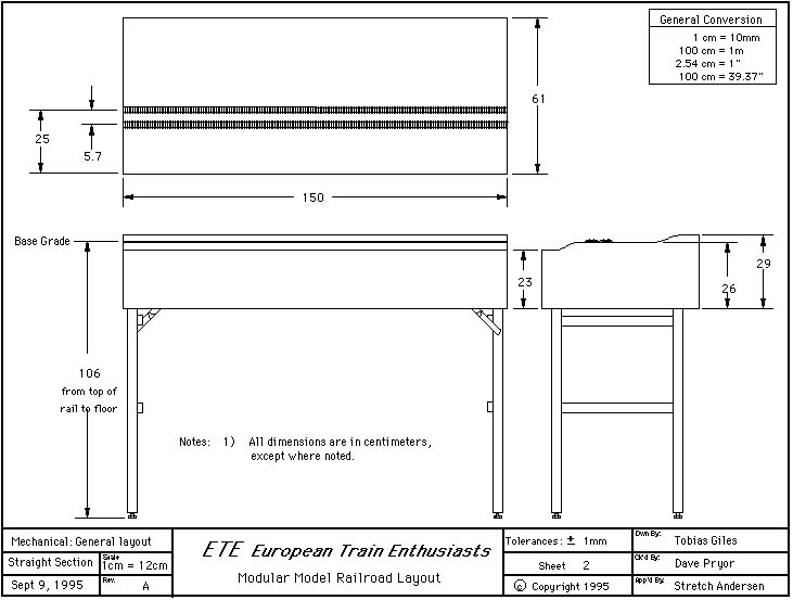
The overall modules dimensions are 150 cm long by 61 cm wide (Sheet #1). The end pieces of all the modules have a mandatory profile (Sheet #2). The up and down profiles on end pieces must be maintained, but the profile of the module may taper up or down over the run of the module. In fact is recommended that the front and rear sideboards be cut originally higher than the end pieces, so tapered “terrain” cuts can be cut with a jigsaw front and back (Sheet #3).
The mating of the end pieces is particularly critical. For this reason, the Bay Area group has made a template available to anyone building a module. Particular care should be taken with respect to the placement of the three module mating holes. (Sheet #4)
The modules are made of 3/4" plywood. For stability, a minimum of five horizontal stringers are recommended. As the module develops, these stringers will be used to attach vertical supports which will hold up the underpinning of the roadbed (Sheet #5).
The bottom of the base module should be 78 cm from the ground. Keeping this distance constant is critical to the interchangability of the drapes which are velcroed on the module.
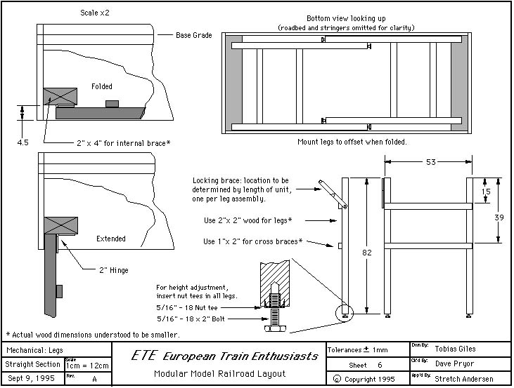
Two horizontally mounted 2 x 4’s provide a stable support for the leg assemblies. (Sheet #6) Legs are generally made from 2 x 2 stock with 2 1 x 2 horizontal braces. Each leg has a 5/16 by 2” bolt inserted in a “T” nut. These bolts provide for height adjustment on floors which are uneven. The two leg assemblies are mounted by hinges in an offset manner so that when collapsed, they fold under the skit of the module. The leg length dimension should allow for a floor to top of rail dimension of 106 cm. When extended module legs are kept open by support hinges places on opposing sides.
The system is designed to run both MARKLIN and NEM norm. The modules consist of two main line tracks running parallel for through trains. Each main line utilizes Marklin "K" track, even though one or both lines may be operating in DC. The K-flex track is electrically isolated for DC operation. Sidings are either DC or AC depending on the owner’s preference, and must be isolated from the main lines regardless of your current (AC/DC) preference.
Not coincidentally, by positioning the inside track at 25 cm from the front of the module, two modules back to back can be connected by the 360 mm radius Marklin's (and other manufacturer's) standard curve. This allows back to back placement of the modules for home use, or perhaps special end curved sections could be developed in the future for setting up in very narrow locations.
In addition, crossovers between main lines should be isolated for all four electrical connections, i.e. each rail, center stud and catenary.
ETE advise caution while planning curves and gradients on the main line. While not discouraged, curves should not have a sharper radius than the corner modules (approximately 24") and are preferably much broader. Even on the 24" Marklin standard curve, long passenger cars have considerable overhang, so for aesthetic reasons curves should be at least a 30" radius. Gradients are also a problem if they're too steep. Long trains, as are the norm on modules, are already a heavy load. Therefore it is recommended track not exceed one or two percent grades.
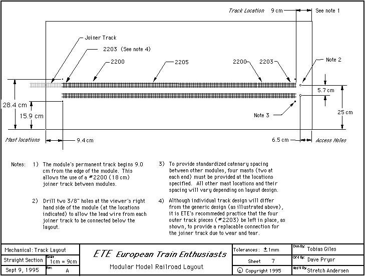
It is recommended to place track as follows: Use Marklin part #2203 30 mm track for each end of the module as a cap to the end of flex track, switches, etc. In use, the track takes a good "beating" and having a small, cheap replaceable section on the end of your module makes good economic sense. It's also easy. The modules are 1500 mm long. Track laid is 1320 mm because 180 mm is used for connector sections. With a Marklin 2205 section of flex track, 2-2200 Marklin track sections and 2-2203 track sections as end caps, track laying comes out exactly 1320 cm (30 + 180 + 900 + 180 + 30 = 1320).
Either Marklin K track or DC code 100 rail should be used for DC sidings, to match the Marklin code 100 rail as well as to accommodate all flange depths. Nickel Silver rail should be used because of its conductive capabilities when oxidized, as well as compatible looks. Marklin K-Track should be used for AC sidings.
All track (and ties) are to be weathered rust color (preferably Floquil brand roof brown). The only exceptions to this are turnouts and uncoupler tracks. Air brushing the track will give a more detailed look. Care should be taken to carefully clean the tops of rails, center studs and any track on which you will solder electrical connections.
All visible road bed and ballast is to be Merkur Styroplast brand roadbed. As of this writing, this product is not generally imported by US hobby dealers, although it is readily available via mail-order from most European hobby shops. Merkur roadbed is “indented” for insertion of Marklin track. Various pieces are available to correspond with the various configurations of Marklin track (switches, uncouplers, etc.) To aid in inserting the track in the roadbed, it is recommended that loose “ballast” be cleaned out of the track/tie indentations before attempting to insert track. A small screwdriver blade works well, and the time spent “cleaning” the Merkur will be more than made up in the ease of insertion of track sections.
Prior to inserting the track into the roadbed, insure that all electrical connections to the to the track have been made. Because Marklin rail is stainless steel, it's all but impossible to solder. Therefore, it is recommended that Atlas rail joiners be cut in half and soldered to the wires leading to the track. Center stud connections can be made by soldering to the base place under the K track. To facilitate soldering (without melting the plastic ties!) you may want to use a Dremel tool to remove some of the black enamel from the baseplate prior to soldering.
K track and Merkur roadbed may be attached to your sub-roadbed plywood with either brads or small screws. It is recommended that you use screws. The reason will become obvious should you ever have to remove and relay any track.
All mainline switches are to be Marklin K "sleek" switches. It is strongly recommended that switch motors are mounted on the under side of the module. (Undermounting kits do not come with switches and must be purchased separately.)
These switches are electrically isolated for both AC and DC running. For truly smooth DC operation the isolated middle sections need to be wired to the appropriate track, however if permanently wired this way, shorts will be caused during AC operation. Therefor these short inner sections of track need to be wired to their respective track with a switch. Once again, because Marklin rail is stainless steel, it's all but impossible to solder. Therefore, it is recommended that Atlas rail joiners be cut in half and soldered to the wire leading to the switch. They can then be carefully inserted under the appropriate rails for a good electrical connection.
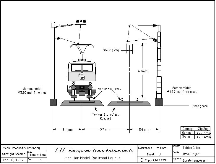
The main lines must have overhead catenary compatible with the Sommerfeldt catenary systems. Non-Sommerfeldt catenary is strongly discouraged for several reasons. Because of the transportation of the modules there is a considerable amount of "wear and tear" that Sommerfeldt, because of its steel construction is better able to withstand. Also, Sommerfeldt is very prototypical in appearance, and masts and overhead wires are available for most European countries. Further, Sommerfeldt masts (unlike Marklin and some other makes) screws completely through the bench work for very solid placement. We recommended that Swiss-prototype "zig-zag" clearances be followed to allow operation for narrow pantograph sliders found on fine scale models, so they don't hang up inadvertently. See the Sommerfeldt construction manual for further clarification on this subject.
Between module joiner tracks are Marklin 180 mm straight K-track sections modified as described below. Clearance of 90 mm from module end to the fixed track end allows for the installation of the 180 mm sections to create a continuous line.
The three-point contact system allows both AC and DC isolated operation, and at the same time establishes common tools permitting quick setup. Each Marklin joiner track is modified as follows:
Once the track is ready it needs to be attached a piece of Merkur Styroplast track ballast as follows:
As shown on Sheet #7 drill a 3/8” hole on both sides of each mainline track through which the center stud plugs will be passed. Female Marklin connectors attached to the appropriate wiring buss connection should be provided on both ends of the module. The holes should be drilled under the ballasted section, at the approximate spot where the wire exits the Merkur.
Each module owner is responsible for providing the ballasted sections as outlined above for both tracks on the RIGHT hand side (as seen from the audience) of his module. Joiner sections must also be provided for any local sidings.
A standard 180 mm section of Marklin K-Track (#2200) is used to join tracks between modules. Each section of track is modified (see note 1 below) and then permanently affixed (white glue) to a section of Merkur ballasted roadbed. The exact manner in which Merkur is cut at each end of the 2200 is critical to insure universally proper mating with other modules (see note 2 below). When fabricated properly, these joiner track sections with their affixed ballast "drop" right into place.
For catenary joiner sections, use Sommerfeldt wire section #141 at 188 mm long, with catenary poles set at 94 mm from module end. The sections should easily hook on to your catenary pole, thus creating a little system tension. (Sheet 8)
In the event that the 188 mm catenary sections are too short or too long due to pole travel or odd- installation (a very common experience in setting up catenary), a .25 gauge phosphor-bronze wire can be used as jumpers for catenary between modules.
The wiring system is designed to accommodate both AC and DC operation. A 12 wire, 18 gauge, buss connects the modules electrically. (The wire currently used is Belden #8466. A supply of this cable has been purchased by the Bay Area Module SIG and is available by the foot at cost.) Figure 1 shows each of the twelve wires, it’s color (assuming the Belden wire mentioned above is used) and its’ purpose.
An intra-module “pigtail” connection of approximately 12 inches should be left on each end of the module. Each end of the cable is affixed with 12 pin polarized interlocking plug connectors. Also note that because of the way the plugs mate, the wire positions appear reversed on the male and female plugs. Care must be taken to insert the correct wire in the right hole. Misplaced pins can be removed with an extracting tool. Better to get it right the first time!
Since the electrical integrity of the entire layout is dependent on a good solid buss, great attention should be paid to the makeup of these electrical connectors. Each of the twelve wires should first be crimped and then soldered onto the male of female pins used in these plugs.
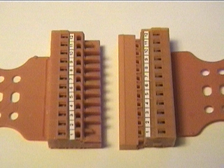
Figure 2 - New plugs. (female on the left, male on the right)
Somewhere in the length of the module, the buss cable should be cut, and both ends of each wire inserted into one side of a 12 position “European style” barrier strip (Radio Shack # 274-679). Into the other side of the barrier strip (or distribution strip), wires run to the track, studs, catenary, K-83 decoders., etc. “Local” wiring should utilize 20 gauge stranded copper wire. (You will most likely find that Marklin or Brawa are the easiest suppliers.) To aid in trouble shooting, local wiring should conform to the “Marklin” color code standards as follows:
Red - center stud and catenary current
Brown - ground from tracks (+/- DC)
Yellow - power to lights and solenoids
Blue - ground return from solenoids
Gray - accessory ground
To help insure electrical integrity, all wire splices should be soldered and then taped or covered with shrink tubing. When “Marklin” type plugs and sockets are necessary, the wire clamped in them should first be tinned with solder. All wiring should be neat and secured to the module underpinning with wire clips and/or wire wrap ties. Staples should be avoided, as they can cut through insulation and cause shorts.
If you are planning a local siding on your modules, you should consider installing the second “local” buss If you use the same type of plugs for your local buss, be sure to swap male/female ends to differentiate from and avoid confusion with the main module buss.
In future installments, signals, scenery and more.
We look forward to having you join us!